Table of Contents
- The Sandwich Theory
- The Escher Sandwich
- Draw priority overview
- The problem
- Circuit behavior - in emulation
- Conclusion
Welcome to the fourteenth article of the Sonic Battle (GBA) Renderer series.
The Sandwich Theory
I figured that using painter’s algorithm the draw priority would be:
- First floor tilemap
- First floor drop shadows
- First floor walls and objects, depth sorted
- Second floor tilemap
- Second floor drop shadows
- Second floor objects, depth sorted
Also illustrated in the frame breakdown in article #5.
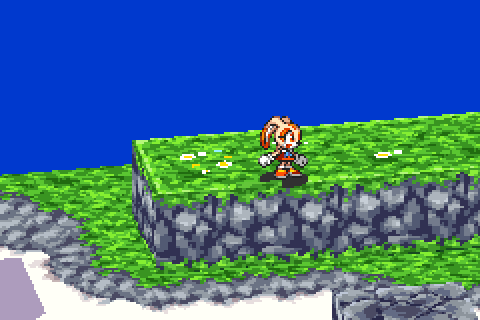
The core idea is that the two tilemaps sandwich everything else that belongs on the first floor.
The Escher Sandwich
I confirmed the theory with mGBA’s debug tools.
(Quick aside - Drop shadows are treated no different from usual objects, I was wrong about that one. They have no “reserved” draw order.)
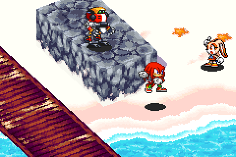
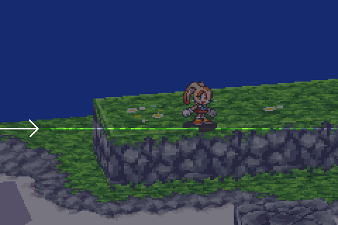
And so I went on my merry way until I noticed this situation:
At play here are two walls (outlined), the top tilemap, and the drop shadow (outlined):
All walls should be sandwiched between the tilemaps. But here the left one is drawn on top of the drop shadow which is drawn on top of the tilemap. How?
I checked the draw priorities again and they’re not the issue.
Time to hit the books…
Draw priority overview
Draw priority is done in hardware as depicted below (OBJ Processing, BG Processing, and Draw Priority Evaluation circuits). Behavior tied to hardware usually has some distinctive limitations… so we can already expect some gotchas.
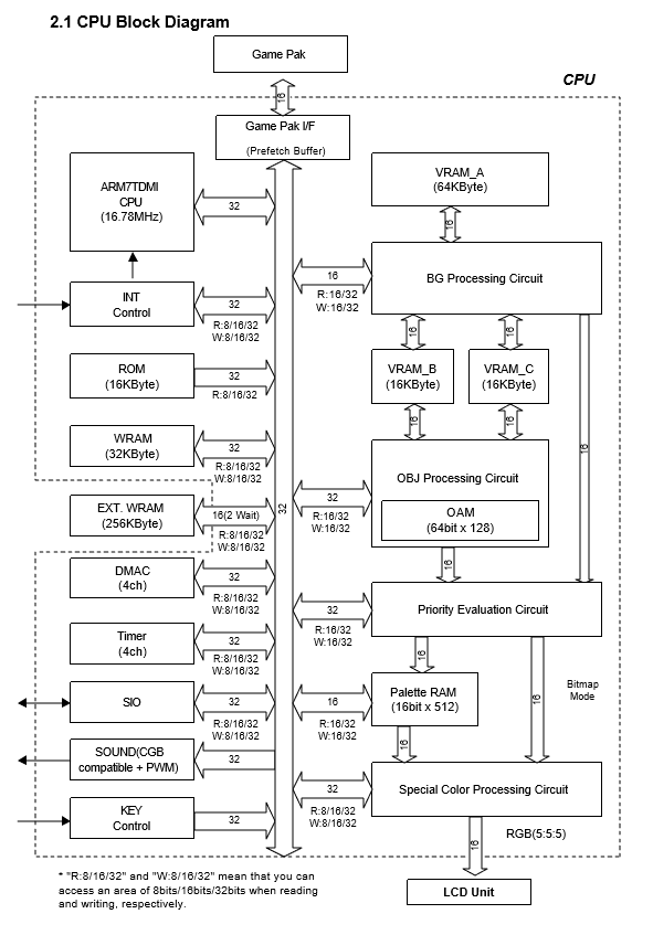
From the AGB Programming Manual, Version 1.1
The manual describes its usage as follows:
(OBJ is equivalent to “hardware sprite”. OBJ number is the location of the sprite in memory, from 0 to 127. BG is equivalent to “tilemap”.)
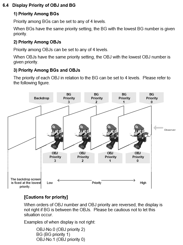
From the AGB Programming Manual, Version 1.1
The problem
So in summary two things affect a sprite’s draw priority:
- Draw priority (the lower priority is drawn first)
- In-memory location for tie-breaking (the lower in-memory location is drawn first)
- Sprites should be grouped in-memory by draw priority (if there’s a separating tilemap) (and the groups themselves ordered by draw priority)
Number 3 is the stern cautionary paragraph near the bottom.
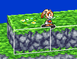
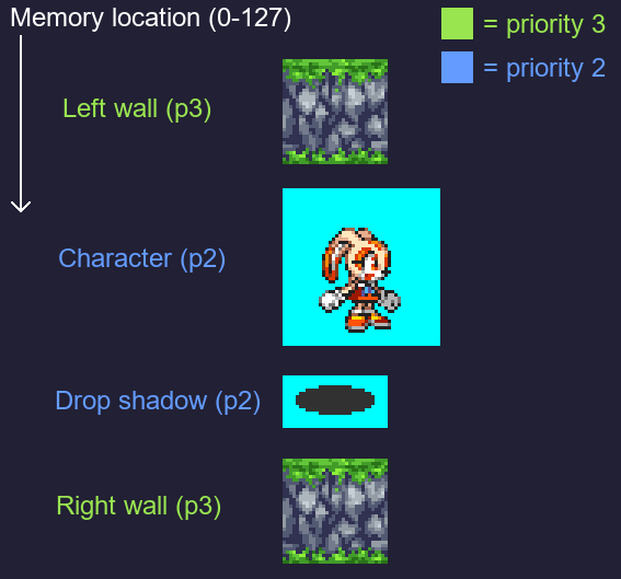
So let’s observe the problematic case again:
Here’s the in-memory sprite layout that I can see with mGBA’s inspection tools:
![]()
BG 2 & 3 are just markers for reference, they're not contained in the sprite layout
This layout doesn’t respect cautionary paragraph #3, and that trips up the hardware and causes the Escher sandwich. It doesn’t seem to be intentional as the draw priorities are still set correctly. Even the in-memory locations are correctly set for tie-breaking the character and the drop shadow, it’s only the grouping which is wrong.
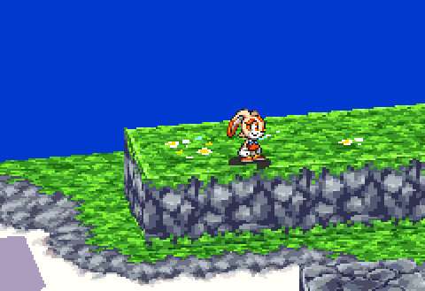
Here’s what a safe layout would like for the same scene:
![]()
Circuit behavior - in emulation
Ok fair enough. But why?
Disclaimer: I won’t touch on the actual circuits, I’ll only rely on mGBA’s source code. I made sure to verify that the Escher sandwich occurs identically in the mGBA, VisualBoyAdvance-M, and no$gba emulators, as well as in Nintendo’s very own GBA emulator on the 2DS. So I’m fairly certain that whatever logic mGBA is emulating behaves accurately with respect to hardware.
Render loop
Here’s an abstract summary of the render loop (only the parts which are relevant to the situation):
- For each of the screen’s horizontal lines (called scanlines, there’s 160 of them):
- For every OBJ in memory (from location 0 to 127):
- Pre-process current OBJ (only if its bounds intersect this scanline)
- For every priority level (from 0 to 3):
- If any OBJs were pre-processed for this priority level
- Post-process OBJs for this priority level
- Render tilemaps for this priority level
- If any OBJs were pre-processed for this priority level
- For every OBJ in memory (from location 0 to 127):
OBJ pre-processing step
mGBA keeps a buffer of pixels for the current scanline. This buffer is reserved for OBJs only. A pixel in this buffer contains the RGB color as well as some rendering flags (they include the OBJ’s priority level).
This step renders the OBJ to that buffer. For every pixel it checks the priorities against the existing pixel (if any) before writing, using it like a depth buffer or Z buffer on top of a color buffer. Once this step executes for all OBJs mGBA has essentially finished rendering OBJs and prioritizing them amongst themselves (for the current scanline).
HOWEVER transparent pixels are handled in a very counter-intuitive manner. They don’t modify the current pixel’s color at all but still “promote” the current pixel (if it has been written to at least once before) to the transparent pixel’s priority level. Here it is in the source code: in a function that renders a single pixel to the scanline buffer.
If this transparent pixel priority level promotion didn’t exist then it would have been just a classic depth buffer without any OBJ memory location shenanigans.
It must be either a hardware particularity or a conscious decision on Nintendo’s part to support alpha masking for example.
Don’t worry if this is a bit unclear so far, I added visualizations a bit further down which help a lot.
OBJ post-processing step
This step iterates through the OBJ scanline buffer and copies the pixels belonging to the specified priority level into a general scanline buffer. Tilemaps also write to the general scanline buffer in subsequent steps.
The OBJs’ in-memory locations don’t matter at all in this step as the ordering information is only being obtained from the OBJ scanline buffer, from the earlier pre-processing step.
OBJ pre-processing visualization
I improvised some logging for mGBA to visually “step through” the construction of the OBJ scanline buffer.
I’ll use our familiar scene as an example:
Let’s inspect scanline 91:
Here’s the memory layout of the OBJs we care about:
(The cyan pixels represent transparent pixels)
Visualization continued
Here’s the construction of the OBJ scanline buffer step by step:

The thin white lines separate the steps. The thick white line separates the color buffer from the priority level buffer (in grayscale: lighter gray = lower OBJ priority = drawn on top of darker gray pixels).
Here are the steps:
- The left wall OBJ is drawn with priority 3.
- Transparent pixels from the character OBJ are drawn with priority 2. They don’t modify the color buffer BUT they promote the overlapping pixels that the left wall drew to priority 2 (woops).
- Opaque and transparent pixels from the drop shadow OBJ are drawn with priority 2. The shadow gets clipped on the left side by the wall pixels that got promoted in the previous step (oh no!).
- The right wall OBJ is drawn with priority 3. It gets clipped by the right side of the drop shadow OBJ which is the intuitive behavior - no complaints.
When it comes to compositing the OBJs with the tilemaps in a later process, we find that a portion of the left wall now renders on top of the wrong tilemap due to its level order promotion (oh no!). This is what the GBA programming manual warns us about specifically.
Conclusion
The game’s code doesn’t conform to the platform’s specs which can cause draw priority issues.
The bug could have remained in the final release because:
- The developers most likely had bigger fish to fry. This bug has a very limited impact all things considered.
- The specific manual used by the developers maybe didn’t contain the cautionary paragraph. It wasn’t present in the first few editions of the English manual for example.
This is the last article in the series (excluding the appendices) but it’s not over yet! I haven’t finished writing all the previous articles so I’ll be publishing them gradually.
You can subscribe to the mailing list to be notified when a new article appears.